
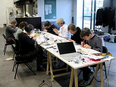
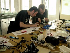
Simple hack on USB webcam opened this astonishing microcosmos to us in Hackteria workshop by Andy Gracie and Mark Dusseiller.
The main reason being in Bergen was however a kind invitation from Gisle to Jürgen, Bengt and myself to present Ohanda initiative to Piksel audience. Good discussion, more elaborated draft as an concrete outcome of that.

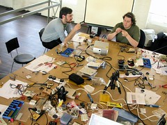
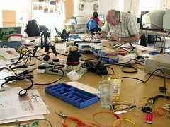
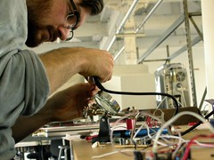
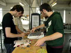
GOSH – summit & workshop was one intensive gathering of diverse thinkers & makers around the still fluid topic of open hardware. Three-day summit followed the five-day workshops and indeed grounded open hardware from various angles from practices to licensing.
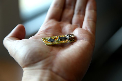
Above Brian Evans’ Modified Pico, Arduino -compatible microcontroller we managed to assamble.
The workshops were run by the participants and catered us rich buffét of ongoing open hardware projects, hands on tools&skills sessions and discussions. The summit program gathered more experts around and presented more academic insight on the subject matter. Inspiring, almost overwhelming in the middle of spectacular Canadian Rockies.

Ravi, Gisle, Susan, Jon, Chris, Bengt, me, Jürgen, Daniel, Jessica, Brian, Alex (out of >30 of us)
Some of us hit our heads together for tackling the somewhat complex issue of open hardware repository and the licensing schemes that it would require. With the help of Ravi’s knowledge on copyright law and trademarks we gradually sketched down a membership based community where different license options are available for OSH -projects & products. Community would be open to everyone who accepts the terms of use. Documented open hardware projects would available in three different categories, free (no limitations), open (eg. for non-commercial use) and accessible (for proprietary, but useful information like electronic manufacturers documentation). Jürgen further consulted CC lawyer for valuable improvements for this proposed model. Community was named as OHANDA – Open Hardware and Design Alliance. Ohanda would act as a certificate, like Fairtrade™, on open hardware products, in quite the opposite way from the warranty-void stickers, challenging and provoking for opening the product and improving it.
Hopefully soon something will be up and running for dialogue and development with the rest of all you who are interested. For now, GOSH!-wiki is the forum.
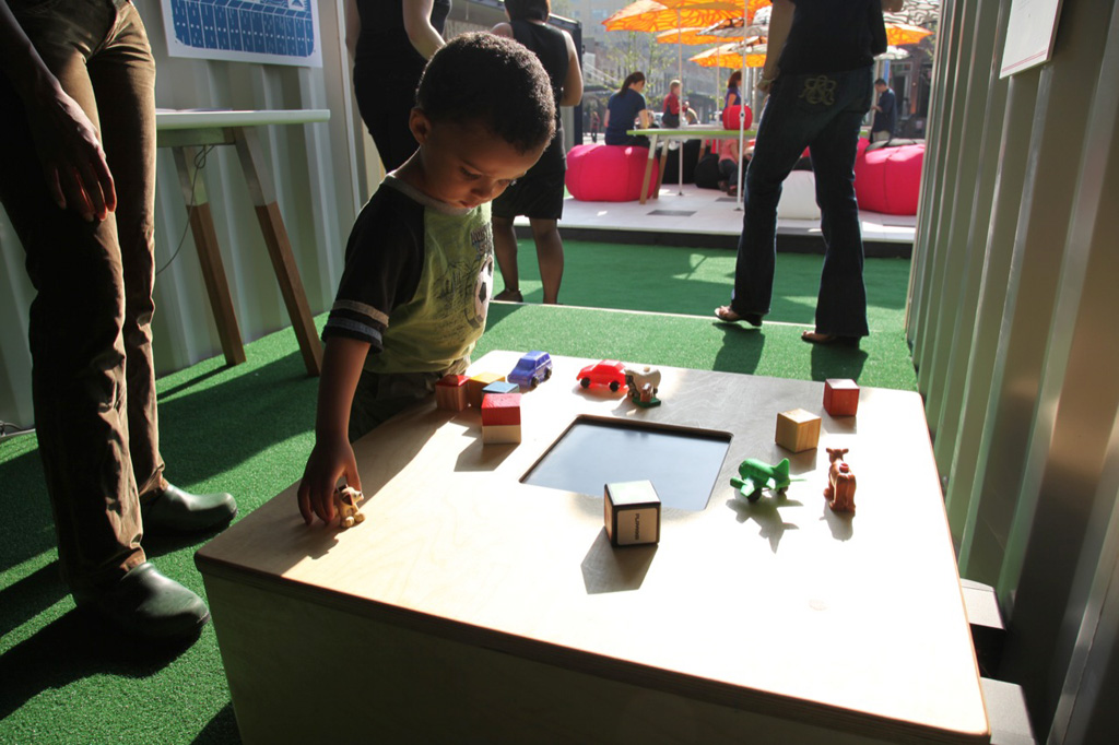
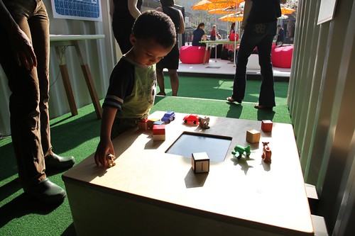
Playkka is being exhibited in New York Design week as a part of Playful – New Finnish Design exhibition at Meatpacking district until monday 18th. The Finnish invasion spreads around the district in cargo containers filled with fresh projects from Finnish designers with a focus on play and creativity as elementary forces in human life.

Apart from my screen almost melting under the sun, the first day was well nice. Lot of people flaneured on the streets in über-trendy Meatpacking and bumped in to us & our containers. Still bit struggling to filter genuine interest from many Americans who seem to be so amazed after every sentence said so not quite sure is Playkka really that wonderful. Tomorrow we give a solar sound workshop for kids with Dan. Bit worried on the clouds in the sky and the grim forecast.
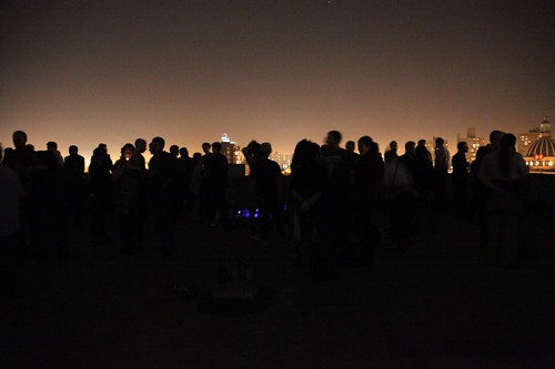
The nice but sweaty first day got a perfect ending in a rooftops of Williamsburg chilling with good friends.
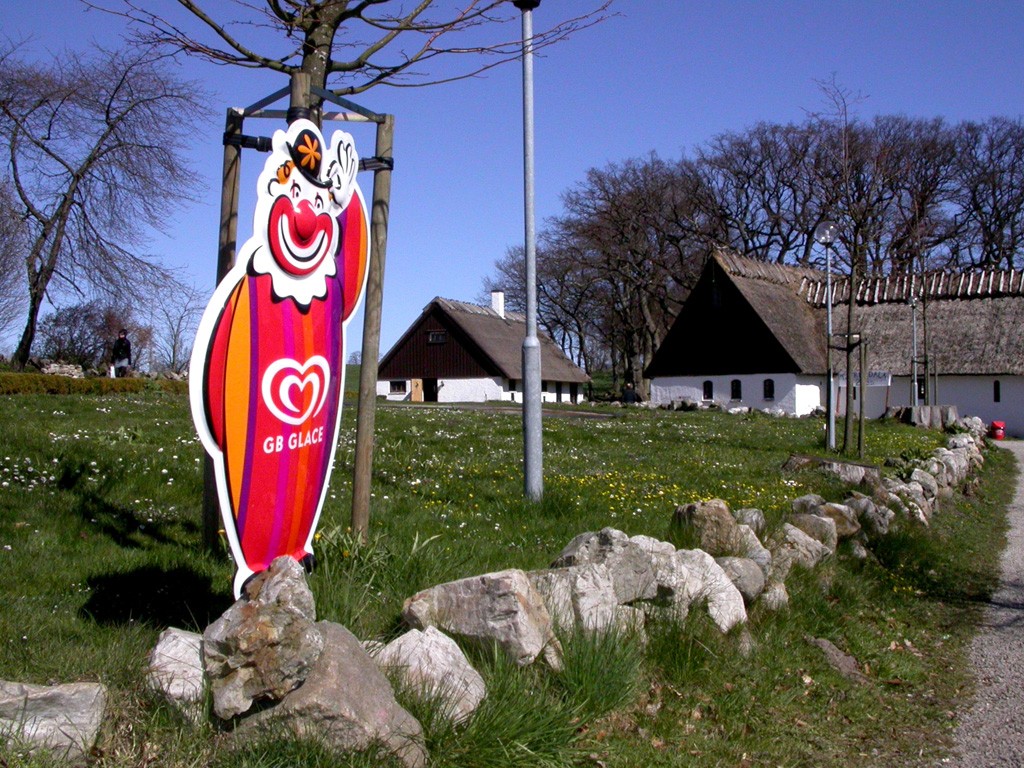

Artists in the Archipelago (AiA) delegation of ours toured eastern Skåne in Sweden for a couple of days, visiting their Konstrundan. Dating back to 1968 ÖSKG Konstrundan has grown to a nine-day event and draws tens of thousands of visitors every year. The concentration of artists and crafters in relatively small area is amazing although they represent quite a traditional set of methods and subjects. Newer artforms are missing, even photography and video seem to be too contemporary or perhaps just more difficult to sell. Mixed media and installation art are also mere curiosities in the pictoresque gardens.

Indeed, life seems overly happy under blossoming magnolias of Skåne. When the world around us is spinning downward in ecological and economical crisis, there is little of that visible in their art. Shouldn’t reflection of the world be integral part of art? Beauty and hope are absolutely necessary but we should not escape the reality. Not us, we who can make the invisible visible and document our time with so diverse voices.

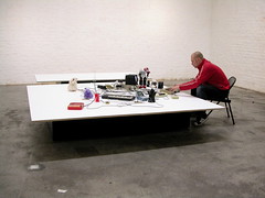
But beauty we saw, some great humor as well, Sven-Åke Ekbergs amazing miniatures to name a favorite of mine (Kassa Balans, Cash Balance, pictured above). And the houses and gardens, tasteful, rustic and prosperous, just like in the magazines.
But just when we are about to announce in unison our intentions to move all here immediately and live happy ever after eating apples we gaze out to the open Baltic Sea and one thing stands out. There is no archipelago! Welcome to Finland we say.
Still, a word of appreciation, Thank you Skåne for all the positive energy we got from you.
We Love Technology Salon, by BASE in Huddersfield once again brought together nice pack of thinkers and makers. Creative misuse of technology, spatial mapping of social networks, worlds first “Satcom”, artificial creativity, “Inverted Pyramind of Stuff” among others were visited through snappy presentations, leaving one quite overwhelmed in inspiration while me and Dan presented a glimpse of our RFID projects in process.
Meeting Yuri Suzuki was particularly interesting due his line of work. Beautiful, funny and playful musical things and his work with oh-boy-are we-fanboys Maywa Denki. Hope to see some collaboration in future with him.
Lisa Roberts from Blink is the lady behind this wonderfull event. Make friends with her, little bio below:
When she isn’t organising We Love Technology and programming the Social Technologies Summit for Futuresonic, Lisa designs socially-inclusive mobile technology initiatives using SMS, MMS and Bluetooth. As the codirector of Blink, since 1999 she has collaborated with Andrew Wilson on a raft of short film initiatives including NESTA-funded, made-for-mobile short film production fund Pocket Shorts which for two years helped new filmmakers explore the impact of mobile technology on the future of film making and distribution. In 2005 Lisa co-developed Bluevend, a unique Bluetooth vending machine designed for the wireless distribution of made-for-mobile phone content which went on to tour Film and Video Umbrella’s Single Shot film commissions across the UK after opening at Tate Britain. Lisa is currently working on Blueloci, a new Bluetooth system which will provide visitors with a deeper understanding of key works at the Yorkshire Sculpture Park. Lisa Roberts is a founder member of BASE.

My first encounter with Alternative Party, demoscene get-together was a nice surprise. Quite impressive event with geekiness, dedication and pure laid-back fun. I did demonstration with Koelse in bending and electronic noise, great fun. Tried also streaming video from phone to Bambuser from sunday ceremonies, bit useless footage, nice service though.
Random niceness:

sunlight vs children of the night


Janne Pulkkila / Radioactive music (scroll down)
… and a wonderful software from Kitchen Budapest Animata

Pachube is a web service for routing dynamic data-feeds between user-made input&output nodes. I can for instance start to feed by home temperature to Pachube and someone somewhere can use that in realtime for pitch control. Why, why not? Or I could grab the price/oil barrel feed from those available and make a twisted connection to my radiator for anticpating the rocketing electric bill.
Configuring Pachube with Processing and Arduino with Firmata seemed first bit overwhelming after a quite a break from these apps. But it went surprisingly smoothly. Strangely enough, my biggest problem was just to upload the Firmata to Arduino. I’m using one of the earlier Arduinos and just loaded the latest software (012) which produced some undefined reference to timer0_overflow_count. After random googling, just a bit older version (009) uploaded the Firmata smoothly.
Edit: Indeed, as pointed out in this thread, I also followed the instructions blindly and managed to replace the working firmata included in Arduino 12 with older version. Now all seem to work nicely: Older Arduino (Arduino Extreme 2 I think) + Arduino 12 + Processing 1.0.1
The Pachuino example file worked nicely, some hassle with port forwarding with our ADSL and the pipeline between my tiny LDR and the world was clear.

Our “School” took part of ENO treeplanting day and we planted four oaks on our yard.


Sauma -exhibition opened at DDC with TileToy in it. The show will be open until January 2009 so plenty of time for that this time. We, me and Dan, are still looking for opportunities to make the needed next generation prototype, the one that could actually be manufactured. Waiting for that, some new nice design interventions have been added to Sauma show:

Bugia by Arihiro Miyake

“Tanssitossut” by Aamu Song & Johan Olin

Fireplace by Ilkka Suppanen

A version of Mouse Labour project is being exhibited at Yrke, konstnär -exhibition in Parainen. This time the detailed recordings of mouse use are presented as high-resolution prints. The show itself portrays artists working in remote locations in South-West Finland and is part of Konstrundan 08 event.

My newest work-in-process, “Playkka” -play prototype is exhibited in Naantali Vanha Raatihuone from July 1st to 15th. Playkka is a play-test -platform to study play process with tangible interface, namely tagged objects. It is a table with four RFID readers, screen, audio and a pile of play items. The current alpha-alpha version does very little but might lead to new discoveries in “smart” play environments. Far from unique approach, the excellent and inspiring research by Timo Arnall and his students to name one source of inspiration.
Process description (in Finnish)
Article in Turun Sanomat (in Finnish)
Video

First experiment of routing 2D graphic with High-Z S-400 CNC mill. The line graphic was exported as generic EPS from Freehand, converted with Cenon to HPGL format which opened to WinPC-NC milling software. Some hassle was with defining machine & workpiece coordinates and the end result was quite a bit off from 1:1. My short visit to Dan’s über-equipped “Polymer Technology Laboratory” restricted me from further studies this time. However, I hope I can get my own CNC building project back on track now.
Sauma exhibition has returned to Finland from the US tour. The exhibition and our TileToy with it is open in Design museum in Helsinki until March 2nd.
My latest DIY electronic instrument workshop took place two days after the Osasto-G opening. Most of the participants turned up and all got their Nandsynths made during the short intensive day. Lot of first time solderers again so nicely done indeed.
The fixed tutorial doc is here and I posted some useful links on the resources category under the Workshops. I’ll keep adding new stuff there so stay tuned.
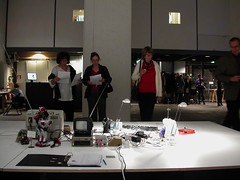
My latest installation Osasto-G is now up and running in ForumBox with media installations from Hanna Haaslahti and Heidi Tikka. Opening was a success, lot’s of people turned up so warm thanks for all of you who made it! Due to our big move to our new house, I have to postpone more detailed writing on the work and the process after the things settle down. The show runs until December 29th, check it out!
More photos on my Flickr. Video here.

“OFFLOAD is the UK’s first network media and systems arts event on nature, sustainability and ecology. The event brings together international, national and local artists and practitioners interested in creating work that use new and existing media. OFFLOAD is interested in interactive, playful, participatory and socially aware practice.”
I’m presenting Mouse Labour here with Juha and took part on a panel: “THINGS TO COME: Designing New Tools for Action” with Kate Rich and Nicolas Henninger / Exyzt.
Introduction
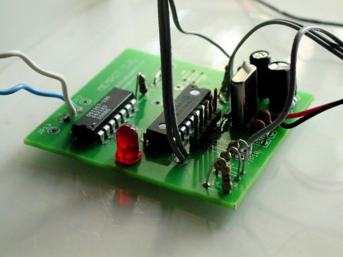
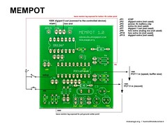
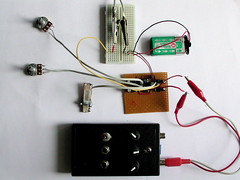
MemPot was developed by Dan Blackburn and me as a control interface for circuit bent instruments and sound generators. MemPot is a built around PIC 16F819 microcontroller that reads analog resistances, records them to memory and plays them back via digital potentiometer DS1267 chip. The memory buffer size and the playback speed can be adjusted.
The first PCB
MemPot was the first circuit design we finally got one proper PCB made for us. That was rewarding experience, although not without any problems. I learned myself the widely used Eagle CAD software during the design process and there are couple of things that I missed. Firstly, by mistake I chose too small resistor packages from the library, so the 6mm long, most common resistors, don’t fit horisontally but must be soldered vertically. Not a big thing luckily. The other is bit more inconvenient. I forgot to put extra solder points for GND and +5 used in the interface (outside the board) so when wiring the switches and pots, the GND and +5 must be wired to exposed points on the board. Coincidentally the exposed legs of vertically soldered resistors turned out to be just fine for this, so the first mistake kind of solved the second one.
Making it
- picture of the schematic (version 1.0)
- schematic and board file in Eagle format (version 1.0)
- PIC code (V1.0)
- example videos in YouTube
Making the MemPot with the PCB is straightforward. Solder the parts in any oder you like, I have usually done the chips first. There is a ICSP socket for updating the PIC code, so using IC socket is not necessary. If you are concerned of damaging the chips, use sockets for the PIC and the digital potentiometer chip. If you don’t have PIC programmer with ICSP port, you naturally need to flash the PIC first and use socket in order to update the software.
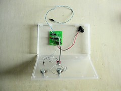
When you are done with the board, you can test some of it before doing the interface. If you power the board, the LED for indicating setup mode blinks few times and then turns off. Next is the interface. Before wiring the switches and pots, you need to make some decisions for the case and see how long wires you need from the board to the panel. Drill the holes for the pots, switches and the LED and attach them to the panel. Wiring them to the circuit is easier when they are fixed in place on the panel. Solder the wires according to the diagram below.
Using it
MemPot is a controller, so you need something to control. Simple sound maker like the NandSynth or APC with resistance controlled pitch will do. If you have some circuit bent instruments with pot or LDR controlling something, hook MemPot to that. This first version of MemPot has two outputs of 100K resistances of which we are using one. You can put larger physical pot in series with the digipot output to change the range, to 500K-600K instead of 0K-100K for instance.
Power up the board and the preset buffer should play, linear ramp of 0-100K resistance in loop. Adjust the playback speed from the speed pot. Hold down the rec button and tweak the rec pot, LED starts blinking. When you release the rec button, the recorded tweaking should loop. MemPot overdubs, so when the buffer gets full, it overwrites the memory from the beginning. You can change the buffer size by entering to setup mode from the toggle switch. LED lits when in setup mode. Now you can use the speed pot to change the buffer size. Try very short by turning the pot almost all the way counter clockwise. Exit setup mode from the toggle switch, the very beginning of the previously recorded buffer should play.
Improvements
The indication of speed and buffer size does not exist. I have used serial LCD screen or PC to debug the values, but simple gauge from few LED’s would do as well. For closed case, a power switch and power LED would make sense. Toggle mode for overdubbing vs one-time recording would be useful together with sync signal from one extra pin on every pass of the starting point of the loop.
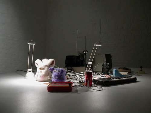
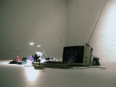
Osasto-G | Gizmo Asylum on diorama unohdetuille elektronisille esineille. Rakastetut ja vihatut elektroniset laitteet viettävät ansaittuja eläkepäiviään kaltaistensa saurassa, museoituina, mutta myös viritettyinä kommunikoimaan keskenään. Heitä pällistelemään tulevat ihmiset, entiset käyttäjät ovat enää katsojia, mutta samalla myös katsottuja.
Onko elektronisilla esineillämme myös salainen elämänsä. Ne näkevät etäisyystunnistimin ja kameroin, ne kuulevat mikrofonein ja tuntevat nappiensa painallukset. Ne reagoivat ja prosessoivat tuntemaansa ja kommunikoivat meille takaisin. Juuri heidän ohjelmoitu logiikkansa tekee elektronisista esineistä erityisiä esineitä. Niiden ulkoisen olemuksen, muotoilunsa lisäksi, niillä on oma käyttäytymisensä. Tämä käyttäytyminen on usein merkittävämpi tekijä meidän ihmisten suhteessamme niihin, heihin, kuin ulkoinen muotokieli. Tiedämme, ettei heillä ole omaa oikeaa identiteettiään, mutta mielellämme mielessämme luomme heille sellaisen. Toivomme ja projisoimme tietokoneisiimme, puhelimiimme ja robotteihimme inhimillisiä piirteitä.
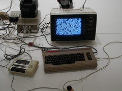
Installaationi koostuu eilispäivän elektroniikasta: tutuista leluista, soittimista, mikrotietokoneista, peleistä, puhelimista, televisioista, radioista ja kameroista. Teknisiä vempaimia joita on käytetty tunteella. Niitä on rakastettu ja niille on annettu lempinimiä, niitä on yritetty ymmärtää ja ne on paiskattu seinään kun siinä ei ole onnistuttu. Nämä esineet esitetään galleriassa kuin täytetyt eläimet eläinmuseossa. Ne on luokiteltu ja niistä on esillä tekniset spesifikaatiot, mutta toisin kuin täytetyt kolleegansa, ne elävät.
Olen laajentanut esineiden ohjelmoitua logiikkaa kuuntelemaan ja näkemään eri tavoin, vastaamaan toisilleen, ja tilassa liikkuville ihmisille liikkeen, äänen ja valon avulla. Dramaturgia perustuu havaintoihin ja eri reagointivaihtoehtoihin. Koska joukossa on useita esineitä, näistä vaihtoehdoista koostuu monimutkainen verkosto, johon katsoja alkaa kiinnittämään vaistomaisesti syy ja seuraus -suhteita sekä inhimillisiä piirteitä. Se tulkitaan vuoropuheluksi, joka näyttäytyy omaehtoiselta kun vaihtoehtoja on riittävästi.
Temaattisesti teos käsittelee esinekulttuuria, kulutuskulttuuria, muistojamme ja suhdettamme esineisiin sekä ennenkaikkea teknologiaan. Osittain teos perustuu Anthony Dunnen ajatukselle käytön estetiikasta (“aesthetics of use“), minkä mukaan elektroniset esineet rikastuttavat elämäämme jos niiden (tietokoneohjattu) vuorovaikutus on valjastettu edistämään alati kehittyvää ja vivahteikasta suhdetta kanssamme, toiminnallisuuksien ja käytettävyyden lisäksi tai jopa niiden sijaan. Näin käytön estetiikka käsittelee esineen ulkomuodon sijaan sen käyttäytymistä.
Taustalla ovat myös toiveemme jaetusta elämästä älykkäiden robottien kanssa. Robotiikan todellisuus on tänäpäivänä jo ällistyttävän pitkällä mitä motoriikkaan ja koordinaatioon tulee, mutta emotionaalisuus ja erityisesti todellinen älykkyys on vielä tavoittamattomissa. Haen emotionaalista kontaktia enemmänkin elämää imitoimalla, tai tarkemmin hyvin pienen elämään liittyvää tunnetta mallintamalla. On selvää että esineeni eivät ole älykkäitä, mutta niihin samaistuminen voi tapahtua hyvinkin vaatimattomilla eleillä. Mekaaniset, itseohjautuvat esineet muistuttavat meitä ajankohtaisista turvallisuuteen, valvontaan ja sotateknologiaan liittyvistä ja tiheeän uutisoiduista innovatioista. Arkipäivään ilmestyy vähitelleen yhä monimutkaisempia ja kyvykkäämpiä laitteita miehittämättömistä lentävistä pikkuroboteista silmäleikkauksia tekeviin apukäsiin, joille annetaan vastuuta enemmän ja enemmän. Pian kohtaamisia tai törmäyksiä näihin apureihin alkaa ilmetä arkielämässämme.
Teos sivuaa myös tavara- ja kulutuskulttuuriamme, esineiden käyttöikää ja kierrätystä. Uusien laitteiden käyttöikä lyhenee, ne piiloutuvat teknisen monimutkaisuuden taakse, emme saa emmekä osaa niitä enää avata saati korjata. Kun ensimmäisiä koneita rakennettiin, olivat mekaaniset osat usein näkyvillä ja koneen toiminnan logiikan ymmärsi sitä hetken katseltuaan. Nykyään kone on pienentynyt mikropiiriksi ja sen logiikka on piilossa monimutkaisissa virtapiireissä ja patentein suojatuissa salaisuuksissa. Auto korjataan palauttamalla piirilevy tehtaalle, ei autotallissa jakoavaimellla. Kärjistäen, teknologiset laitteet toimivat mystisesti ja niitä ymmärtävät vain niiden suunnittelijat, pitkälle erkoistuneet insinöörit. Jotta elämä elektronisten laitteiden keskellä, ei vain laitteet, voisi kehittyä, on ihmisillä on oltava pääsy osaksi suunnitteluprosessia, ei testiryhminä tai kuluttajina vaan suunnitteljoina, kokijoina ja kertojina.
“When an objects use is subverted, it is as though the protagonist is cheating the system and deriving more pleasure than is his or her due. The subversion of function relates to a breakdown of order; something else becomes visible, unnameable, unable to find a correspondence in the material world.”
– Anthony Dunne, “Design Noir – The Secret Life of Electronic Objects”
Beeps, waves and bass lines workshop took place in DRU studio in Bates Mill, Huddersfield. Six participants plus me and Dan had intensive three days with making electronic instruments namely the Nandsynth and MemPot controller. Feedback was positive from the participants regardless of some dark moments of debugging the circuits.
For improving the workshop a few remarks: Working with stripboard vs ready-made PCB for first soldering job is bit challenging. Since making PCB’s is an extra expence, pre-cutting the strips and marking the component places will solve this equally. Again, I think I underestimated the time needed for completing work in workshop context. Keeping the workshop schedule on time while solving unavoidable problems is more difficult point of improvement. I feel my time management is still not in balance. All suggestions from the participants are most welcome here.
Workshop material is online and I will publish the revised tutorial sheets as soon as I check the changes.
Thank you again, Rob, Frank, Dave, Rees, Jordan, Robert and Dan!

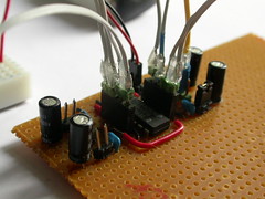
The first batch of MemPot PCB’s arrived. This was a Eagle learning process and there might still be mistakes in the design. The learning curve for Eagle was a bit steep, with three different editors: library, schematic and board, all interconnected. Good tutorials are available and after a days slow reading while doing paid off and it started to make sense. Lot of the work was finding correct libraries for different components and making some of myself. Due to the fact that many libraries seem to be done by the Eagle users, there are some inconsistencies with naming, package, wire and pad sizes. This, and the various requests from the PCB manufacturer was quite confusing but it seems that they matter mostly when doing delicate multilayer design with very small / sensitive components. Big old-skool DIL design with microcontroller and few resistors and caps is more forgiving. Still, one PCB needs to be soldered to see if it really works.
The Eagle CAD files are here. I hope I can post the final verdict on the success of this design later this week.

Sauma exhibition where TileToy is exhibited is opening at Architecture and Design Museum of Los Angeles on Friday 29th of June. Check the TileToy blog for more.

Introduction
This experiment is based on an example in Nicolas Collins’ book: “Handmade Electronic Music, The Art of Hardware Hacking”. The motivation for this experiment is to learn IC logic chips and to prepare inexpensive experiments for sound making electronics workshops. This is a first version, please be aware of possible errors. All corrections and contributions for improvement are highly appreciated. This post will be updated.
The misuse of Quad NAND Gate 4093 chip makes simple & cheap way to synthesise modulating square waves. Misuse, since the 4093 chip was not designed to make sounds but to do boolean logic, as a member of highly successful CMOS 4000 series IC chips form late sixties.
A single NAND gate has two inputs and one output. The 4093 chip has four NAND gates, hence the name QuadNAND gate. The NAND stands for one of the common boolean logics (Not AND) where two input states, highs(ones) or lows(zeros), define the state of the output. In NAND case, if neither of inputs are high (being low) the output keeps high. If both of the inputs are pulled high the output inverts to low. If one of the inputs is low the output is always high. The chip uses Scmitt Trigger comparators, which provides noisless & direct swapping of the states.
To turn this to sound it helps to understand basics of the sound. To put it very short, when there is changing states there is frequency. If the frequency oscillates through air and is in the range of hearing, there is sound. If we do the above mentioned state swapping we generate oscillation, a square wave signal of highs and lows, which can be amplified and heard.
Basic square wave can be made with just one NAND gate. The first input is connected high(+5 to 15V) the second is connected low(GND) via capacitor and the output is fed back to the second input via resistor. The chain of events in a fast loop:
- input1 is driven high, the input2 is low, making the output high
- the high output recharges the capacitor in time affected by the feedback resistor
- charged capacitor pulls the input2 high, output goes low, capacitor discharges
- back to the beginning
The frequency generated is based on the capacitance and resistance of the components menitoned above. Increasing the resistance with eg. a potentiometer, less current will flow to capacitor, slowing the “swapping”, lowering the pitch. The higher the capacitance, the longer it takes to recharge, forcing the range of the sweeping pitch lower. This experiment uses 100k pots with 0.1uF and 2.2uF caps. The big cap keep the range very low, in rhythmic clicks, where the small one takes the range high in clear pitch frequencies.
NAND gates can modulate each other. By connecting the output of gate1 to the input1 of gate2, the swapping high-low cycle enables and disables the second gate very fast while the the second gate produces its own frequencies. This can be fed further to the gate3 and so on. This results to complex square wave modulations worth experimenting so read on.

Making it
This configuration can be done with breadboard, which is highly recommended for experimenting the logic first. For this first version, I used stripboard and connectors for changing between two caps and inserting variable resistors. Wiring here can be simplified. I have all wires on component side for clarity. This circuit works for me, this explanation is not proofed, build it with your own risk and please report any errors to me.

1. Solder the 4093 chip with enough space on the sides. Using socket is always wise. I chanced it here. Old CMOS chips are sensitive to static so be aware. Solder the GND(black) wire to pin7(lower left) and the +V(red) to pin14(top right) notice the chip orientation from the marker on the top. Remember to cut the strips from the solder side between the pins, see 3b.

2. Solder the two caps between input2(pin2) and gnd. Put the smaller cap closer to the chip, break the connection from bigger cap to ground and solder jumper pins over that break. When jumper is connected the bigger cap goes in parallel with the smaller cap, “overriding” the smaller cap and switching the pitch range to very low end. Solder the output1(pin1) to +V. This connection can be replaced with jumper/switch if you want to trigger the synth sound externally. If you use the same stripline for the cap gnd and the pin1, remember to break it on the solder side!

3. Solder the 4way connector (or wires) to the pins2-5, right besides to the chip. This gives us resistor insert points for gates1&2. Wire the output of gate1(pin3) to the input1 of gate2(pin6). Solder the main power pins or battery clip to +V and GND strips on the top. At this point you can try to test the first gate by putting a resistor in the socket between the pins 2&3 and taking signal from pin3 to the tip of the audioplug and commong GND from the board to the sleeve. Notice the warning of using mains connected amp in section 6 below.

3b. Remember to cut the “multiused” strips from the solder side if using stripboard or wire all the necessary connections if using dot-board. (Sorry for the blobby soldering, I’m still struggling with my new leadfree solder.)
At this point you can try to test the first gate by putting a resistor in the socket between the pins 2&3 and taking signal from pin3 to the tip of the audioplug and commong GND from the board to the sleeve. Notice the warning of using mains connected amp in section 6 below.

4. Solder the caps to the gate2, between pin5 and GND, same jumper break as before. Solder the output of gate2(pin4) to the other side to input1 of gate3(pin8).

5. Solder the caps, jumpers and sockets for gates3&4 accordingly. Check the 4093 specsheet for pin order. Solder the header pins to all gate outputs (pins3,4,10,11), the green headers in the image. Notice, these are the signals for the tip of the audio plug to amp. You need to take the common GND from the board to the sleeve of the audio plug.
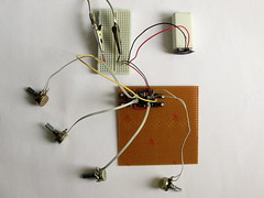
6. Wire the pots / resistors / LDRs to the sockets. Double check the solder points for shorts to strips next to them and use magnifier to check that cutted strips are properly disconnected. Power up the board, feel if the battey or the chip warms up, if so disconnect and look for shorts. Take the audio signal from gate4 output(pin11) to amp together with common GND. Signal is loud, be aware. Caution! Broken amp connected in mains can give an deadly electric shock when using exposed wires. Build simple battery powered amp with LM386 chip like this, or use battery powered active pc speakers if unsure of your amp.
Using it
Start with the first gate, varying the resistance between pins2&3. Take the audio out from header in pin3. Try the difference with a jumper enabling the bigger cap in gate1. Move to gate1 modulating gate2. Put another pot between pins 4&5 and move the audio out signal to pin4 (gate2 output). Experiment with the pots and cap jumpers. Carry on to gate3 and gate4.
Instead of a potentiometer as a controller, you can try different variable resistors. Slider, like mixer fader gives very quick interface of varying the resistance, close to scratching speed. LDR or photoresistor can give gestural control when blocking and revealing light hitting to it.
If you want more automation, you can build the Memory Pot from our earlier examples, where the pot turns are recorded and playdback with variable speeds.
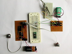
Or you can build simple sequencer varying the resitance in discreet steps like in the SwitchSequencer example below. Check also the videos of our experiments.

Thursday 12 July 2007
The Media Centre, Huddersfield, West Yorkshire
Compered by Matt Locke
Commissioning Editor for New Media and Education, Channel 4
Led by pioneering technologists and artists working in areas such as interactive architecture, sound and games, We Love Technology presents the latest adventures in the creative use and misuse of technology. In a bid to encourage a more human-centric future WLT07 presents a full day of informal presentations, workshops and performances and experimentation in the creative control over technology.
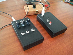
MemPot is a small controller circuit where potentiometer (or any variable resisor) is read and recorded with PIC (16F819) microcontroller. PIC stores a sequence of values from the user turning the knob and plays the same sequence back via serially controlled digital potentiometer (DS1267) chip. The playback speed and recording buffer can be controlled. This is a handy tool for performing gestures with electronic instruments with variable resistors as controllers.
Same circuit can naturally be experimented with other variable resistors or analog sensors as inputs. LDR’s, bend sensors or even accelerometer movements could be recorded and played back similarly. If the resistance changes are not continuous but in steps, the playback resembles simple step sequencer. Follow the various experiments from the oikosulku-blog:
- example videos in oikosulku blog
- picture of the schematic (version 1.0, not tested!)
- schematic and board file in Eagle format (version 1.0, not tested!)
- PIC code (V1.0)
MemPot was developed by me and Dan for our circuit bending activities and to use as a workshop project on analog sound synthesis. We can hopefully include the making of MemPot for our next DRU workshop in July.
MemPot documented here.
(DRU July 2007 workshop materials page, participate! and check for updates)
Documents
Specsheets
- 4093 Quad NAND gate Schmitt Trigger
- PIC 16F819 Microcontroller
- DS1267 Digital Potetiometer
- LM386 Audio Power Amplifier
- 40106 Hex Schmitt Trigger
- 555 / 556 Timer
- 4017 counter
- 4066 switch
MemPot
- Introduction (comment here)
- Schematic (jpg, not tested!)
- Eagle schematic & board file (not tested!)
- PIC code (V1.0)
Books:
- “Handmade Electronic Music : the art of hardware hacking” by Nicolas Collins
- “Timer, Op Amp, and Optoelectronic Circuits & Projects” by Forrest M. Mims III
- “Physical Computing” by Dan O’Sullivan & Tom Igoe
Links:

(Draft 1, subject to change)
Day 1.
- introduction to workshop, background
- creative misuse of cheap logic chips for sound/noise making
- square wave & modulations from CD4093 NAND gate, schmitt trigger
- square wave & modulations from 555-timer (aka Atari Punk Console)
- options for additional modulations, interference and filtering
- experimenting on breadboard, notes for own instrument
Day 2.
- planning own instrument based on previous experiments
- soldering own instrument on stripboard
- soldering simple amp&speaker unit
- testing & debugging
Day 3.
- introduction to MemPot, Potentiometer with memory
- soldering MemPot PCB kit
- using MemPot for controlling own instrument
- the most annoying jamming session ever
- where next
Beeps , waves and bass lines
The Media Centre / Price : £30 (to cover materials cost only)
Tuomo Tammenpää + Daniel Blackburn
Three-day workshop on using and misusing analog and digital electronics and controllers for sound synthesis. By the end of the workshop you will be given all you need to take home your own electronic instruments of bleeping strangeness. Breadboard prototyping, PCB-soldering, simple PIC programming and most annoying jamming with kilo hertzs. Some previous skills on electronics will help but not absolutely essential.