Introduction
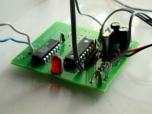
MemPot was developed by Dan Blackburn and me as a control interface for circuit bent instruments and sound generators. MemPot is a built around PIC 16F819 microcontroller that reads analog resistances, records them to memory and plays them back via digital potentiometer DS1267 chip. The memory buffer size and the playback speed can be adjusted.
The first PCB
MemPot was the first circuit design we finally got one proper PCB made for us. That was rewarding experience, although not without any problems. I learned myself the widely used Eagle CAD software during the design process and there are couple of things that I missed. Firstly, by mistake I chose too small resistor packages from the library, so the 6mm long, most common resistors, don’t fit horisontally but must be soldered vertically. Not a big thing luckily. The other is bit more inconvenient. I forgot to put extra solder points for GND and +5 used in the interface (outside the board) so when wiring the switches and pots, the GND and +5 must be wired to exposed points on the board. Coincidentally the exposed legs of vertically soldered resistors turned out to be just fine for this, so the first mistake kind of solved the second one.
Making it
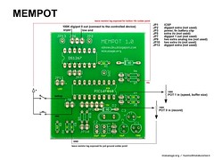
- picture of the schematic (version 1.0)
- schematic and board file in Eagle format (version 1.0)
- PIC code (V1.0)
- example videos in YouTube
Making the MemPot with the PCB is straightforward. Solder the parts in any oder you like, I have usually done the chips first. There is a ICSP socket for updating the PIC code, so using IC socket is not necessary. If you are concerned of damaging the chips, use sockets for the PIC and the digital potentiometer chip. If you don’t have PIC programmer with ICSP port, you naturally need to flash the PIC first and use socket in order to update the software.
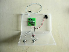
When you are done with the board, you can test some of it before doing the interface. If you power the board, the LED for indicating setup mode blinks few times and then turns off. Next is the interface. Before wiring the switches and pots, you need to make some decisions for the case and see how long wires you need from the board to the panel. Drill the holes for the pots, switches and the LED and attach them to the panel. Wiring them to the circuit is easier when they are fixed in place on the panel. Solder the wires according to the diagram below.
Using it
MemPot is a controller, so you need something to control. Simple sound maker like the NandSynth or APC with resistance controlled pitch will do. If you have some circuit bent instruments with pot or LDR controlling something, hook MemPot to that. This first version of MemPot has two outputs of 100K resistances of which we are using one. You can put larger physical pot in series with the digipot output to change the range, to 500K-600K instead of 0K-100K for instance.
Power up the board and the preset buffer should play, linear ramp of 0-100K resistance in loop. Adjust the playback speed from the speed pot. Hold down the rec button and tweak the rec pot, LED starts blinking. When you release the rec button, the recorded tweaking should loop. MemPot overdubs, so when the buffer gets full, it overwrites the memory from the beginning. You can change the buffer size by entering to setup mode from the toggle switch. LED lits when in setup mode. Now you can use the speed pot to change the buffer size. Try very short by turning the pot almost all the way counter clockwise. Exit setup mode from the toggle switch, the very beginning of the previously recorded buffer should play.
Improvements
The indication of speed and buffer size does not exist. I have used serial LCD screen or PC to debug the values, but simple gauge from few LED’s would do as well. For closed case, a power switch and power LED would make sense. Toggle mode for overdubbing vs one-time recording would be useful together with sync signal from one extra pin on every pass of the starting point of the loop.